CHANGING THE KA24E TIMING CHAIN
Reference Picture
Click to enlarge
PARTS
Chain [13028-8B000]
Tensioner [13070-40F06]
Tensioner Guide [13091-40F03]
Straight Guide [13085-40F10]
The Two O-Ring Seals [15066-5E500] & [15066-40F11]
Front Seal [13510-53J10]
Permatex Blue #6B
Oil (4-Quarts)
Antifreeze/Water Mix
Oil FilterOptional and Recommended:
Cam Gear [13024-40F00]
Crank Gear [13021-53J00]TOOLS
Assortment of Metric Sockets including 27mm For Crank Pulley
Assortment of Metric Wrenches
Assortment of Metric Allen Wrenches
Channel Locks (Adjustable Groove Pliers)
Philips #1 & #2 Screwdrivers �" Bladed (Flat-Tip) Screwdriver
Long Breaker Bar Torque Wrench
Claw Hammer Oil Filter Wrench
Catch Pan 18" Motorcycle Bungee with hooks
6" 3-Arm Puller Long Bar (Floor Jack Handle/Hoist Handle)
Flexplate tool (Automatic Transmission Only)PROCEEDURE
1 - Disconnect and remove battery.
2 - Remove intake pipe at/between MAF sensor and Throttle body.
Remove valve cover hose and <2> hoses about 8" in front of throttle body.
3 – Disconnect <2> connectors at MAF and air temp. sensors, and the <3> at/near the coil.
4 – Using pliers, squeeze retainers for harness from under top half of fan shroud.
Lay harness over passenger fender.
5 – Remove top half of airbox. <4> G-clips and <1> hose clamp.
6 – Disconnect <2> hoses below and slightly behind coil.
*Remember* the white stripe goes in front of the purple when connected.
Undo associated clips, and across shroud. Lay both hoses over passenger fender.
7 – Disconnect <2> hoses from top/rear of charcoal canister (behind driver’s headlight).
Lay both hoses over passenger fender.
8 – Remove passenger side radiator mount. Keep bolts with mount.
9 – Remove lower fan shroud. There are <2> clips (<1> each side). Squeeze to release.
10 – Remove upper fan shroud screws <4>. The upper <2> are right on top, and the lower <2> are very low on the sides.
11 – Disconnect overflow tube from below/near radiator cap. Lay over passenger fender.
12 – Disconnect upper radiator hose from radiator, keeping loose end up.
13 – Push back, and pull up while maneuvering shroud up and out of engine compartment, being very careful to not damage any of the radiator fins. Keep screws with shroud.
14 – Re-attach the upper hose to radiator to keep mess to a minimum.
15 – Loosen <4> 10mm nuts from cooling fan.
16 – Remove belts.
P.S. – Loosen <2> 14mm bolts on top idler.
Alt./W.P. – Loosen <2> 12mm bolts on upper alternator, removing the front bolt.
Label it in a bag.
A/C – Loosen <2> 14mm bolts on bottom idler.
17 – Remove top idler/bracket. Keep bolts with bracket.
18 – Remove <4> 10mm nuts from fan. Keep fan, nuts/washers, and water pump pulley together.
19 – Remove power steering pump bolts <4> 14mm. <1> top/rear, <3> front.
Use bungee to pull P/S pump out of way by hooking one end to pump, and the other end to the passenger front wheel opening.
20 – Remove P/S pump bracket. <3> 12mm bolts. Keep these bolts and the <4> 14mm bolts with the bracket.
21 – Remove distributor cap <2> screws. It’s not necessary to remove the wires, just pull the cap, and push it back out of the way.
22 – Remove valve cover <8> bolts. Keep bolts with cover.
Remove front STB if so equipped.
23 – With the car in Neutral, use 27mm to rotate (clockwise only) crank pulley to TDC 0deg. Look at the distributor rotor. If pointing at you, then turn crank <1> more full revolution. If pointing at drivers side lower suspension, then you are in the right spot.
24 – Manual – Put car in 5th gear, with E-brake pulled tightly. This will give you the greatest mechanical advantage.
Automatic – I’m sure there is some sort of ‘inspection’ cover for the flexplate. Remove it, and using a tool designed for turning the flexplate, have a friend hold the flywheel right here.
25 – Using 27mm with long breaker bar, loosen front crank bolt till it can be turned by hand. Loosen bolt till it starts to ‘wiggle’ freely. Then break loose cam gear bolt using correct size wrench/socket.
26 – Put car back into Neutral.
27 – The pulley probably moved a little, so move it back to 0deg. by hand.
28 – Being careful of the radiator fins, using a 3-arm 6" puller, remove crank pulley, and bolt. Keep bolt with pulley.
29 – Mark lines for distributor base-to-timing cover relationship. This will allow you to easily put the ignition timing back where it started later.
30 – Remove distributor. <2> bolts, and <1> connector (top/front of head). Keep bolts with distributor.
31 – Remove oil pump <4> bolts. (<2> long, <2> longer), and spindle. Spindle probably needs wiggled out. Keep bolts and spindle with pump.
32 – Remove <4> 10mm from head down to timing cover. Set at top of a designated area.
33 – Remove <4> front-most oil pan bolts, and loosen halfway the next <1> back on each side. (<4> removed, <2> loosened). Set the <4> at the bottom of the designated area.
34 – Remove alternator adjusting bracket. Set bracket with bolts at the mid left side of the designated area.
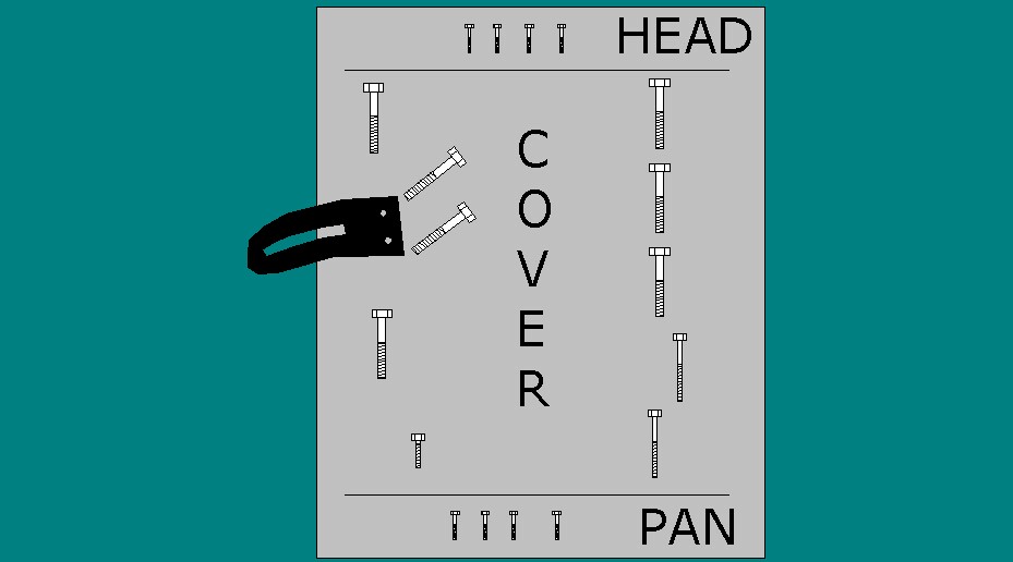
35 – Remove the remaining timing cover bolts, setting them in their respective locations in the designated area. It should look like Figure 1.
36 – There is a small ‘square-ish’ thing bolted behind where the alternator bracket was. There are <3> 10mm bolts holding it on, coming in from the passenger side. <2> visible from the front, <1> under/behind. Remove <3> bolts, and label them in a bag. Use pressure to remove ‘thing’ from side of timing cover.
37 – Using hammer, claws behind the distributor provisions, and the top against the A/C mounting bracket, gently pry timing cover loose from front of motor. At this time, the motor will dump lots of water into the oil pan, and onto the ground/floor.
Now you can see all of the timing components.
If you’re lucky, the straight plastic guide on the drivers side is still there.
If not, then it becomes a really messy affair involving lifting the motor and dropping the oil pan.
38 – Place a shop rag below the crankshaft, ‘sealing’ the open oil pan, to prevent any items from falling into the pan.
39 – Remove the tensioner, and both guides.
Remove chain, and <2> seals.
40 – Clean/scrape gasket surfaces.
If not changing gears, skip to steps 42 and 43, then to 45.
41 – Note relations between spiral gear, and crank gear, and remove both.
Note and remove cam gear.
42 – Using hammer and flat screwdriver, remove front seal, tapping it out from the backside.
43 – Using hammer only, install new front seal, tapping it in from the front.
44 – Install new gears, and spiral gear, without full tightening the cam gear.
45 – Install new chain, matching the silver links with the marks on the gears, then install the guides.
46 – Install tensioner. Remove pin to engage tension. Install <2> seals. Remove rag.
47 – Using hammer and long rod (engine hoist handle/ jack handle) firmly tap down a few places at the front of the oil pan lip.
48 – Apply Permatex to gasket surfaces of timing cover, following directions on the tube.
49 – Apply Permatex to inner corners of head-to-block and block-to-pan.
50 – Install timing cover to block. Insert the top of cover part of the way, then the bottom. This will press the head gasket up, and prevent it from binding/folding. Gently push the cover into place as far as you can. Install the front timing cover bolts in their respective holes, and press the cover all the way on. Install and tighten the <4> head-to-cover and the <4> pan-to-cover bolts. Tighten the <2> loosened bolts for the oil pan.
51 – After giving the Permatex some time to set, remove the alternator bracket and its bolts again.
52 – Apply Permatex to the ‘square-ish’ things surface, then install its <3> bolts.
53 – Re-install alternator bracket, but before tightening, install alternator tightness locking bolt, then fully tighten the <2> bracket-to-cover bolts.
54 – Install crank pulley, without fully tightening bolt.
55 – Insert spindle into oil pump, and align the dot on the spindle gear with the dot/seep hole on the oil pump shaft/body.
56 – Install the oil pump/spindle into the timing cover in the proper orientation, without turning either at all. Install the <4> bolts, and fully tighten.|
57 – Install the distributor, making sure that the rotor is still pointing to the same spot, and the marks on the distributor and cover are aligned. Fully tighten the <2> bolts. Re-attach connector.
58 – Again, put car into 5th gear. Then fully tighten (torque) the crank bolt, and the cam gear bolt.
59 – Install valve cover. Install distributor cap.
60 – Install water pump pulley and fan. Hand tighten nuts as much as you can.
61 – Install power steering pump bracket. Install power steering pump.
62 – Install top idler bracket.
63 – Install and tighten belts. Tighten nuts that retain fan/water pump pulley.
64 – Disconnect top radiator hose from radiator.
65 – Install fan shroud being careful not to damage the radiator fins. Install <4> screws. Re-attach hose to radiator, and tighten clamp. Re-attach overflow hose to radiator near cap.
66 – Route and attach <2> hoses to charcoal canister. They’ll only go one way.
67 – Route and attach <2> long hoses back to the fittings below/behind coil.
*Remembering* that the white stripe goes in front of the purple stripe.
68 – Install upper half of airbox. Install lower half of shroud.
69 – Route and attach harness to MAF sensor, and coil locations.
70 – Install passenger side radiator mounting bracket.
71 – Install intake pipe to MAF and throttle body and valve cover. Attach <2> hoses to fittings 8" in front of throttle body.
72 – Install battery. Reset clock/radio stations as needed.
73 – Drain oil pan.
74 – Change filter.
75 – Pour in new oil. Add your water/antifreeze mix. Top off radiator.
76 – Remove burp valve from intake, or start motor and keep topping off radiator.
77 – Allow motor to fully warm up, watching gauges, then allow to cool. Top fluids.I hope this helps!
Enjoy losing the rattle!
Jason
[email protected]