Blitz Dual Solenoid Boost Controller
(DSBC)
Installation Procedure for Mitsubishi 3000GT
Last updated on 7/7/99
I've put this page together to document the
DSBC intallation for everyone who's interested in. Unfortunately the manual and
instructions came only in japanese and I'm not very good in this language :) By studiing
the 3000GT manuals and with the great help from Chien (Nexus Motorsports), I was able to
do the installation without the japanese manual. He also provided me with a general
installation guide and the setup procedures for the Blitz DSBC.
Disclaimer :
The author is assuming that you are a licensed and certified expert in the automotive and turbocharging field. This sheet is to be used as a general guideline only. The author is not responsible for any liabilities caused by the following instructions.
Installing wiring harness and vacuum tube for DSBC
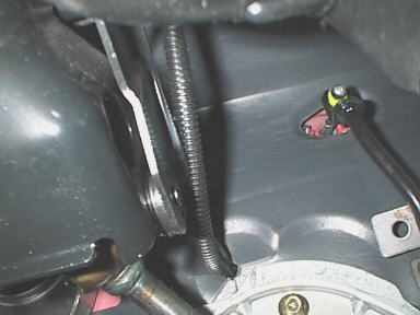 |
I used the small round passage (closed by a
rubber gromet) on the right side of the steering column under the dash to route the wiring
harness and the vacuum tube to the engine compartment (the inner dam is already slotted).
As it is not easy to reach the hole from the engine bay, I used a big screwdriver and
pushed it hard against the rubber piece until it broke in the middle. I had no chance to
remove it from the engine bay (big fat fingers, hehe) but the slotted rubber part is big
enough. The picture shows the small black vacuum tube and the harness already routed to
the hole. Later, I replaced the small tube that comes with the DSBC with a larger hose for the additional boost gauge I mounted next to the controller. |
| First I pushed the tube from the inner-side trough the firewall into the engine bay. Only a few cm were enough as I then was able to reach it with the fingers behind the engine. I did the same with the harness but be sure NOT to pull too hard at the connector !!! But it's easier than it sounds :) On the picture the harness is comming out the firewall behind the wrapped tube. I then routed it up to keep it away from any hot parts. Also the vacuum tube is visible. Due to its less flexibilty it's routed within a larger loop and it then also goes to the passenfers side. | 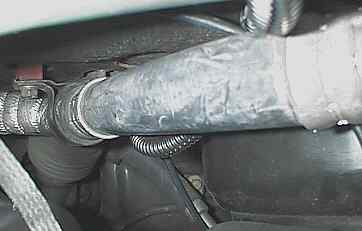 |
 |
Now route the wiring harness to the desired location of the Blitz dual solenoid valves box. Use some ties to hold the harness in position to prevent any burning from hot devices. I placed it along the firewall and tied it to existing tubes (left side of the picture) Then it goes down the washer fluid filler, passes the battery and reaches the solenoid box after the K&N filtercharger. |
| The vacuum tube can easily be routed to the desired location at the purge control hose that's attached to the intake manifold. Just cut the small hose about in the middle and use the supplied T fitting to connect the hoses together. The Blitz vacuum tube can now easily be pushed into the T. | 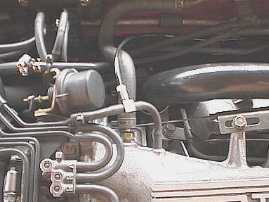 |
Finally route harness and tube to the center console or wherever the controller will be installed. Use some tie-rods for fixing them to prevent them from falling onto the pedals.
Installing the double solenoid valves box
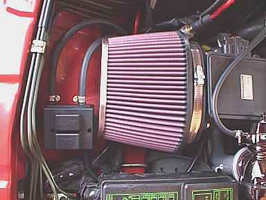 |
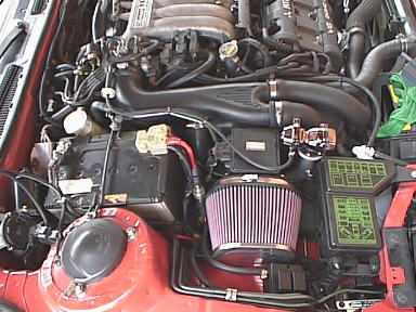
First look out for a good place to mount the Blitz DSV box. Unfortunately there's not many space available for such a box with attached hoses ! I placed the box just infront the K&N filter but maybe somebody else find a better place. Due to this location almost the full lenght of the supplied hose are used. As the hoses are very good quality I do not expect any losses of vacuum or boost. |
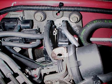
| Now locate the hose that feeds the wastegate actuators and wastegate solenoid valve at the Y-pipe elbow (there's only one). The picture shows it on the left top side of the air-filter for the BOV vaccum line. Just remove the hose from the y-pipe by now. Next attach one of the supplied Blitz hoses to the port on the y-pipe. The hose is slightly too large for the plug but it's ok with by clamp it a little tighter. Route the hose to the Blitz solenoid valve IN port. Now take the other Blitz hose and attach it to the smaller one we removed earlier from the y-pipe. I used another connecting piece as the supplied ones were too large for the stock hose and secured it by tying the assembly to the fuel pressure regulator bracket (upper section of the pic with the second screw clamp). Again route the hose along the IN one to the solenoid valves box and connect it to the OUT port. | 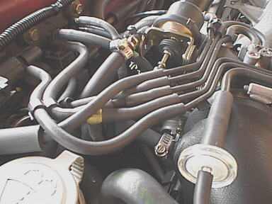 |
| Removing the stock wastegate
solenoid valve out of the path : For the correct operating, it is necessary to unplug the stock wastegate solenoid valve. This because the stock system vents some pressure back to the intake path but any EBC does not ! Therefore, the valve should should be capped to prevent any unfiltered air could reach the intake path.
|
|
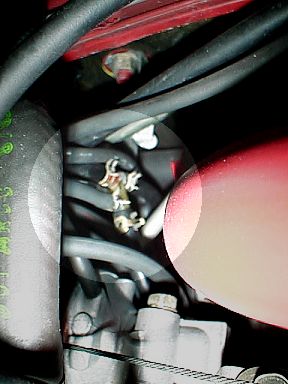
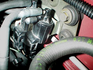
Now locate the two vacuum hoses going down from the stock solenoid valve. One of them leads to the 4-way hose connector just close to the discharge of the rear turbo. In my setup this hose was the lower one, but they can easily be exchanged as the stock system will still work without a problem. If you identified the right hose, pull it from the solenoid valve. Plug the open port at the valve and use somthing to close the hose. I used a plug for the hose and zip-tied it. For the valve a nice cap was found :) That's it ! |
Finally connect the Blitz harness to the Blitz
solenoid valves box harness and your system is ready !
Installing the Boost Controller
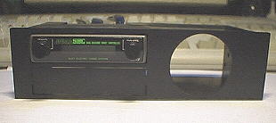 |
I used the Blitz DIN mount for my application. Fortunately the european models already carries a DIN Stereo (I replaced it with a Sony) and I thought installation should be easy. |
The front cover holds a small compartment (was good to put all the tickets into). I removed it (3 screws) from the back and wanted to place the DIN mount into the cover. But it was too small and there would be some unlovely gaps around it. Finally I decided the cut the back piece of the small box and I got a frame that exactly surrounds the Blitz DIN mount. Furthermore I measured the size and mounting brackets and found out that the DIN mount should just "snap" in easily. And it did !
| The cleanest thing I've ever seen :) The controller now just slips in from the back. Attach some of the double sided tape and it would hold there forever (I haven't done this yet). Now use the small gray hose connector and just push the vacuum tube comming from the controller into one side and the vacuum tube comming from the engine bay into the other side. Now connect the wiring harness to the controller harness. Finally attach the black cable to a good ground (e.g. from the Stereo) and the red one to a ignition wire (also from the Stereo, usually red or yellow). | 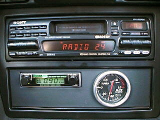 |
Installation is done ! Just put the cover back on and everything is ready for the first test !
Test, Settings and Impression
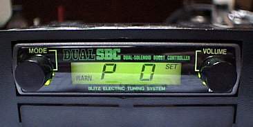
I turned the ignition key and the DSBC was immediatly working by showing 0.00 kg/cm2 (sure, engine was not running, hehe). I've then played with all the functions and finally set the mode to OFF and pushed the volume button until the boost meter showed up. I started the engine and everything was fine. The boost meter showed -47 cmHg and increased when revving it up. I made my first testdrive and checked the boost peak by pressing the volume button once.
It showed 0.42 bar (6 psi) for stock setting. I thought they are set to 8 psi from factory but this is probably one of the differences between the US and European models but also due to the fact the turbos where not spooled up fully. I've then set the #1 Ratio to a value of 20 and recognized a peak boost of 0.52 bar (8 psi) now. The system works !!!
I then played around with it and made several runs including some G-Tech Pro measures. First I've set the warn function to 1.00 bar (14.5psi) But it tooked some times until I reached this boost. To go the save way I've set the WARN limiter to -10 at 1.00 bar and it was interesting how the car felt. At the beep I felt like boost was somewhat reduced and came back after two seconds until the beep was there again. With this setting I've run a new best ET of 13.52@108.5 (G-Tech). HURRAY ! With the bleeder valve (boost was set to 0.72 bar, 10.4 psi) my best was 13.71@105. Great ! But this is not the end of the story. I've then set the warn to 1.20 bar and reduced Ratio only -4. I also increased the value to 65 and set the G-Tech. After the run the peak showed 1.12bar (16.2psi). NEW RECORD : 13.28@110.2 (G-Tech)
Please note : This is not healty as the engine starts to knock after boost more than 1.00bars !
On several testings I runned into a known problem on boosts over 1.10bars as the car started to bog and stumbe around 5000-5500rpms. The problem is the fuel system that runs out of fuel delivery as well as knock that appears after 1.05bars. The hesitation is a typical sign of retarded timing the ECU initiates due to the knock ! Regapping the plugs to 0.034" helped but the the retard was then noticeable at higher boosts. I ranned several times with boosts over 1.2bars with peaks at 4500 up to 1.34bars.
WARNING :
The car runned like hell ..... directly into hell as I just ignored important signs. The later dyno sessions showed that the timing gets retarded more and more when increasing bosot around 5500rpm and therefore power goes down. Until the retard kicks in, the power is amazing but not healthy and will definitely kill your engine. If you don't believe me and not listen to my and others bad experience you can join the rebuild club very soon !
Overall impression:
A great, well developed product on a good price ! It is somewhat complicated to tune in and carrys enough danger to toast your engine. I like it ... but it is not a toy for beginners as you can make too much wrong !
Only points on whishlist : Amber backlight, A/F meter or built in knock sensor device :)
This site is owned by Roger Gerl
![]()
![]()